- Published on
Use Case Diagrams in UML - Definition, Components, Examples & Real-World Usage
Table of Contents
A Use Case Diagram in UML (Unified Modeling Language) visually represents what a system does from the perspective of its users. It shows the interactions between users (actors) and the functionalities (use cases) the system provides.
Instead of focusing on how the system works internally, use case diagrams focus on external behavior—what the system should or should not do.
🧠 Purpose of a Use Case Diagram
- ✅ Define functional requirements of a system.
- ✅ Show who interacts with the system and what they can do.
- ✅ Identify what's in scope and what's not.
- ✅ Make it easy for stakeholders to understand system behavior at a glance.
🎯 It answers the question: “What will the system do?”—and just as importantly, “What will it not do?”
📌 Key Components of a Use Case Diagram
Here's a breakdown of the building blocks of a use case diagram:
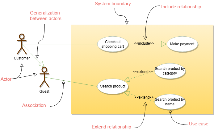
1. Actors
-
Definition: An actor is anyone or anything that interacts with the system (typically a user or external system).
-
Symbol: A stick figure
-
Example: In an online store, actors could be:
- Customer
- Admin
- Payment Gateway (System)
2. Use Cases
-
Definition: A use case is a unit of functionality or business process.
-
Symbol: An oval with the name of the functionality written inside
-
Example:
- Register Account
- Add to Cart
- Checkout
- Track Order
3. System Boundary
- Definition: Defines the scope of the system.
- Symbol: A rectangle enclosing all use cases
- Purpose: It visually shows what's inside and outside of the system.
4. Relationships
➕ Include
- Definition: Indicates that a use case always includes the behavior of another.
- Analogy: Like a function calling another function.
- Example:
CheckoutincludesCalculate Total.
🔄 Extend
- Definition: Shows optional or conditional behavior that can extend the main use case.
- Analogy: Like adding bonus steps to a basic recipe.
- Example:
Place Ordermay extend toApply Couponif a discount is used.
🛍️ Example: Use Case Diagram for an Online Shopping System
                    +-----------------------------+
                    |   Online Shopping System    |
                    |                             |
                    |  (Place Order)              |
                    |  (Add to Cart)              |
                    |  (Checkout)                 |
                    |     ^    ^                  |
                    |     |    |                  |
                    | (Apply Coupon)  (Calculate Total) |
                    +-----------------------------+
                      ^             ^
                    Customer     Payment Gateway
- Customer is the actor interacting with
Add to Cart,Checkout, andPlace Order. Place OrderextendsApply Coupon.CheckoutincludesCalculate Total.
🧭 Real-World Analogy
Imagine visiting a restaurant:
- Actors: You (Customer), Waiter, Chef
- Use Cases: Order Food, Pay Bill, Ask for Water
- System Boundary: The restaurant itself
- Include: Ordering food includes choosing items from the menu
- Extend: Paying bill might extend to 'apply discount' if you're a member
✅ Benefits of Use Case Diagrams
| Benefit | Description |
|---|---|
| 🧠 Understandability | Easy for non-technical stakeholders to follow |
| 🔎 Scope Clarity | Makes it clear what the system will and won't do |
| 💬 Improved Communication | Helps teams (devs, designers, clients) communicate clearly |
| 🧩 Modular Design | Breaks down the system into manageable parts |
| 🔄 Reusability | Common functionalities can be reused through include relationships |
🛠️ Tools to Draw Use Case Diagrams
- Draw.io (diagrams.net)
- Lucidchart
- Creately
- StarUML
- Microsoft Visio
These tools let you drag and drop actors, use cases, and connectors to easily build diagrams.
✅ Summary
A Use Case Diagram is a powerful tool in UML that helps teams visualize and define how a system interacts with external users. It's a high-level functional map that clearly shows what the system should do, helping everyone—from developers to stakeholders—stay on the same page.